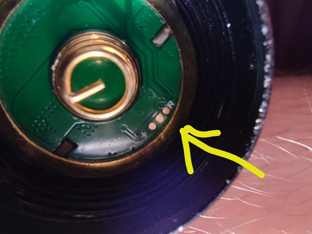
No. The center is ground, the left is battery plus, the right pad is the thermistor used to monitor the battery temperature to make sure it does not overheat during a fast charge cycle. These are likely just pogo pin test points for quality control during manufacturing.
Typically you need at least ground and two data lines to have serial communication. The serial lines will be small traces and will run a similar path along the board. They don’t need to be length/impedance matched in most cases, but they do need to be close to the same length and electrical properties. One is the clock pulse that says when the other is sending the ones and zeros. If the edges are too far off of each other, the communication must go super slow or it will fail. That is just what I look for in practice.
One wire is more for just a few sensors. I think the STmicro stuff has a 1 wire option. At least one of my programmers has a label for it, but with all my hobby stuff, I’ve never used 1 wire for programming. I have only used it for a temperature sensor as far as I can recall. Everything is either JTAG or UART in my limited experience.
So there’s the OneWire protocol that’s for sensors, different microcontrollers will implement a programming protocol using a single wire, which is what I meant.
Jtag has a clock signal, but is generally 5 lines.
My point being that looking for similar trace lengths because one is a clock signal isn’t sound advice. All the common protocols either don’t use a clock signal, or are more than two lines.
Seriously every time this group crosses my feed it makes me so goddamn happy. You guys and you’re incredible niche little love that you know so much about I fucking love it
UPDI used on Atmel micros on Anduril capable flashlights uses a single line for debug and flashing. Much earlier than that, Motorola/Freescale/NXP Coldfire, S12, and some other MCUs used BDM which was also a single wire protocol.
If you want to flash a newer Anduril to this light, look here for hardware and procedures to use those pads.
Wow are you saying this light has updi and a t1616? Nice! I knew that the sp10 pro has that but I had thought the LT1S was older. I just checked my sp10 pro though, and sure enough, it has similar contacts. So this is welcome news. Thanks!
I won’t know for sure without doing a reflash, but I think al177 has the right answer: those pads are for the UPDI system on newer AVR’s, so this is great news once I can get a UPDI dongle. My D4v2 uses an older chip and 6 contact pads. Thanks for the response though!
No. The center is ground, the left is battery plus, the right pad is the thermistor used to monitor the battery temperature to make sure it does not overheat during a fast charge cycle. These are likely just pogo pin test points for quality control during manufacturing.
Typically you need at least ground and two data lines to have serial communication. The serial lines will be small traces and will run a similar path along the board. They don’t need to be length/impedance matched in most cases, but they do need to be close to the same length and electrical properties. One is the clock pulse that says when the other is sending the ones and zeros. If the edges are too far off of each other, the communication must go super slow or it will fail. That is just what I look for in practice.
Aren’t most microcontrollers programmed over UART? AVR has their own one wire programming interface, but neither use clock signals.
One wire is more for just a few sensors. I think the STmicro stuff has a 1 wire option. At least one of my programmers has a label for it, but with all my hobby stuff, I’ve never used 1 wire for programming. I have only used it for a temperature sensor as far as I can recall. Everything is either JTAG or UART in my limited experience.
So there’s the OneWire protocol that’s for sensors, different microcontrollers will implement a programming protocol using a single wire, which is what I meant.
Jtag has a clock signal, but is generally 5 lines.
My point being that looking for similar trace lengths because one is a clock signal isn’t sound advice. All the common protocols either don’t use a clock signal, or are more than two lines.
AAAAH I LOVE YOU FLASHLIGHT LOVING BASTARDS
Seriously every time this group crosses my feed it makes me so goddamn happy. You guys and you’re incredible niche little love that you know so much about I fucking love it
Nope.
UPDI used on Atmel micros on Anduril capable flashlights uses a single line for debug and flashing. Much earlier than that, Motorola/Freescale/NXP Coldfire, S12, and some other MCUs used BDM which was also a single wire protocol.
If you want to flash a newer Anduril to this light, look here for hardware and procedures to use those pads.
Wow are you saying this light has updi and a t1616? Nice! I knew that the sp10 pro has that but I had thought the LT1S was older. I just checked my sp10 pro though, and sure enough, it has similar contacts. So this is welcome news. Thanks!
The programming hardware won’t help because the firmware is closed source.
You don’t need the original source to program a flashlight. If it’s ATTiny based then Anduril has your back.
I agree. If you are able to define the HW specific part of Anduril for this new model you can create a hex file and flash it.
I won’t know for sure without doing a reflash, but I think al177 has the right answer: those pads are for the UPDI system on newer AVR’s, so this is great news once I can get a UPDI dongle. My D4v2 uses an older chip and 6 contact pads. Thanks for the response though!